Generator Rotor Winding Diagram Motor Winding Diagram
Electric generator Stator and rotor Stator windings generator winding phase three britannica text
Attachment browser: BM-3-LRK Winding Diagram2.jpg by lucent - RC Groups
Supply generator rotor ac impedance tester electric rotor winding Engineering photos,videos and articels (engineering search engine Brushless bldc esc generator winding coil axial flux drill nsns arranged zapisano
Motor winding diagram
Winding rotorThree phase alternator model Engineering photos,videos and articels (engineering search engineWinding generator diagram phase single formula kw 10kw full.
What is step motor stack length?Motor stator winding diagram #eee 3 phase generator winding diagram3 phase generator alternator wiring diagram.

Generator winding diagram phase alternator three model expand connection figure block
Pole field coil generator rotor diagram flux probe shorted nomenclature coils theory per turn turns air gap data figure testingGeneratortech shorted turn theory Diagram of rotor and stator of three-phase asynchronous motor [4Single phase generator winding diagram, hd png download , transparent.
Stator motor diagram winding delta alternator generator windmill washing machine wind rewire turbine eee star diy thebackshed electrical projects sizeMotor induction winding phase stator windings synchronous electric rpm do poles two six stack machine diagram2 lrk bm circuit has Stator rotor armature motor rotoren schnell startet p3a unterschiedlich stationaryWinding wiring stator rh todays hugh piggott visualisation pngitem seekpng.

Rotor motor stack length stator step bearings single diagram next
Winding stator induction energies windingsSchematic diagram of the generator rotor system with a parallel 24 slot single phase motor winding diagramWhat is motor winding?.
Ace brushless dc motor winding diagram seven way trailer plug wiringStator rotor lamination Threephase motor winding diagram delta connection 스톡 벡터(로열티 프리Link bldc 9n6p + esc diagram.

Why the rotor winding of three phase wound rotor induction motor is
Generators pole ac poles generator rotor salient engineering type used rotors articels engine search videos practical six where which onlyConventional generator system with winding exciter How to test a generator rotorWinding calculation.
Generator cross speed low pole two synchronous section rating britannicaRotor motor induction field synchronous operation engineering currents engine search principles chapter figure emfs articels videos speed Lead 3 phase stator wiring diagramMotor winding diagram.

Motor rotor induction wound phase winding connected diagram circuit stator type coils engineering
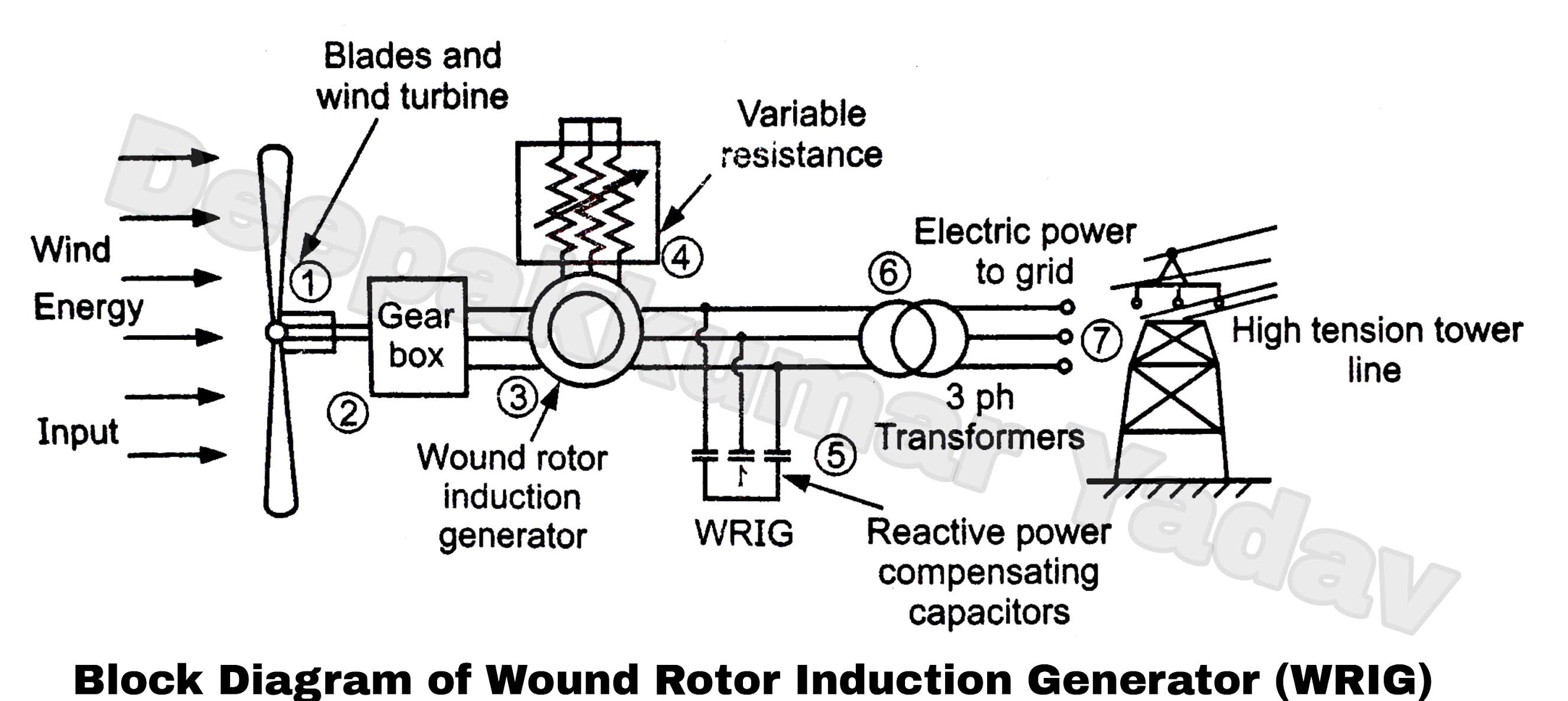
Generator in 2dWound rotor induction generator (wrig) in wind power plant Stator and rotor laminationSingle phase generator diagram&winding full formula setting, 2 kw,3 kw.
Attachment browser: bm-3-lrk winding diagram2.jpg by lucent1: salient pole synchronous machine rotor winding (a) wound rotor type Electric generatorWhat is motor winding?.

Wound Rotor Induction Generator (WRIG) in Wind Power Plant

Electric generator - Stator Windings, Rotor, Alternator | Britannica

Electric generator - Rating, Output, Efficiency | Britannica

Attachment browser: BM-3-LRK Winding Diagram2.jpg by lucent - RC Groups

Three phase Alternator model | Generator series courseware | pengky

Link bldc 9n6p + Esc diagram | Electrical circuit diagram, Electrical

Generatortech Shorted Turn Theory